Process
S-Flex Coupling Selection Method
The selection process for figuring out the right S-Flex coupling necessitates utilizing the charts proven to the following pages. You will find 3 elements to be picked, two flanges and one sleeve.
Information and facts vital just before a coupling is usually selected:
HP and RPM of Driver or running torque
Shaft size of Driver and Driven gear and corresponding keyways
Application or products description
Environmental circumstances (i.e. severe temperature, corrosive problems, area limitations)
Techniques In Selecting An S-Flex Coupling
Step one: Decide the Nominal Torque in in-lb of one’s application by using the following formula:
Nominal Torque = (HP x 63025)/RPM
Step two: Employing the Application Service Issue Chart one decide on the support aspect which greatest corresponds to your application.
Stage three: Determine the Design Torque of your application by multiplying the Nominal Torque calculated in Phase 1 by the Application Services Element established in Stage two.
Design Torque = Nominal Torque x Application Support Issue
Step 4: Working with the Sleeve Overall performance Data Chart two 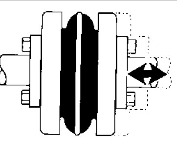 pick the sleeve material which ideal corresponds to your application.
Step five: Working with the S-Flex Nominal Rated Torque Chart three locate the ideal sleeve material column for that sleeve selected in Phase 4.
Stage 6: Scan down this column on the very first entry wherever the Torque Worth from the column is better than or equal on the Design Torque calculated in Stage three.
Refer on the greatest RPM worth in the coupling size to guarantee the application demands are met. If your maximum RPM value is less compared to the application necessity, S-Flex couplings will not be advised to the application.
Note:
If Nominal Torque is less than 1/4 in the coupling’s nominalrated torque, misalignment capacities are lowered by 1/2. The moment torque value is located, refer on the corresponding coupling dimension while in the very first column of your S-Flex Nominal Rated Torque Data Chart 3 .
Phase seven: Examine the application driver/driven shaft sizes to your highest bore size readily available over the coupling chosen. If coupling max bore is just not huge sufficient for that shaft diameter, select the next greatest coupling which will accommodate the driver/driven shaft diameters.
Phase 8: Employing the Item Assortment tables, uncover the proper Keyway and Bore size expected and find the number.